
Domain-Driven Design (DDD) is a powerful method for building complex software that truly aligns with business needs. However, turning business knowledge into a well-structured, actionable domain model is a significant challenge. It requires deep collaboration, expertise, and a lot of time. This is where a specialized DDD modeling tool becomes essential.
Qlerify is an AI-powered domain-driven design tool built to solve this problem. It accelerates the entire modeling process, enabling teams to visually collaborate, define bounded contexts, and generate API-ready models from a simple text prompt. As showcased in a recent Virtual DDD Meetup by Qlerify co-founder Staffan Palopää, our tool bridges the gap between business concepts and executable code.
The session, which even drew questions from DDD creator Eric Evans himself, demonstrated how AI can generate a complete workflow, identify domain events, map out commands and aggregates, and ultimately produce a tangible domain model. This article provides a detailed, step-by-step guide to replicate that process, showing you how Qlerify can serve as your central DDD modeling tool.
To follow along, log in to Qlerify or sign up for a free trial. Once logged in, create a new project, start a blank workflow, and follow this walkthrough.
Note: This guide focuses on using Qlerify as a domain-driven design tool. For a broader introduction to our features, see the Event Storming walkthrough.
Before you begin, ensure you have created a new blank workflow and have an empty canvas in front of you. In an empty swim lane, you should see two buttons: "Add start point" and "Generate workflow with AI".

Next, open Workflow Settings by clicking the cogwheel icon (⚙️) located above the empty diagram. Navigate to the Cards tab and review the Card Type Settings:
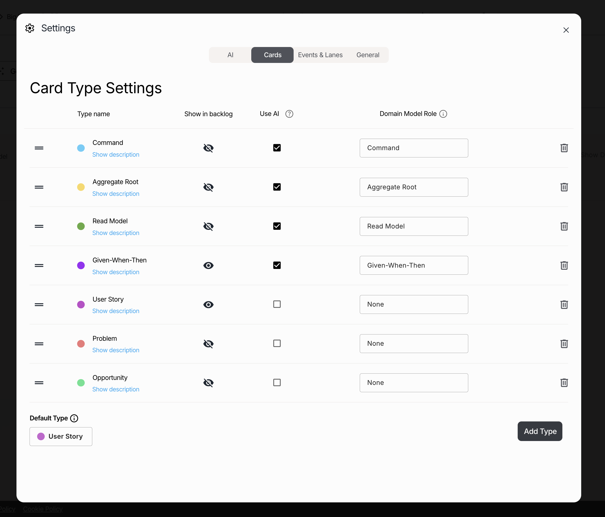
If you wish to change the LLM (Large Language Model), you can do so in Workflow Settings → AI. In this example, we use ChatGPT-4o.
Close the Workflow Settings window. If your workflow is empty, the "Generate Workflow with AI" button will be visible. Click this button and select the following prompt (or enter your own):
Next, ensure the following checkboxes are checked:
Deselect any other check boxes. Then click the "Generate Workflow" button. The generation process may take a few minutes to complete.

Once the process finishes, the LLM will have generated Domain Events, along with cards for Commands, Aggregate Roots and Entities. The Domain Events are placed on a timeline and distributed across swim lanes. Your resulting workflow should resemble the example image shown below (though variations due to the AI are expected).

At this point, each step (Event) in the generated workflow should include exactly one Command card and one Aggregate Root card. Click on an Event to select it and inspect its cards in the sidebar.

The Aggregate Root card can either contain a simple text label with a descriptive name, or it can be linked to an Entity. If the card displays an Entity name within a grey, rounded element (with a dropdown icon to the right), it is linked to that Entity. If the Aggregate Root card displays a link icon (🔗) next to a text label, it is not linked to an Entity.

If not linked, you can click the link icon (🔗) and select an Entity from the dropdown list (or generate an Entity). Selecting an Entity replaces the simple text label with a link to the formally defined Entity.
Navigate to the Entities tab located under the workflow diagram area. Here you can see the generated Entities including details such as field names, and primary key, required and example data. Here you can also generate additional Entities base on free text descriptions. Later we will see how to define relationships between Entities.
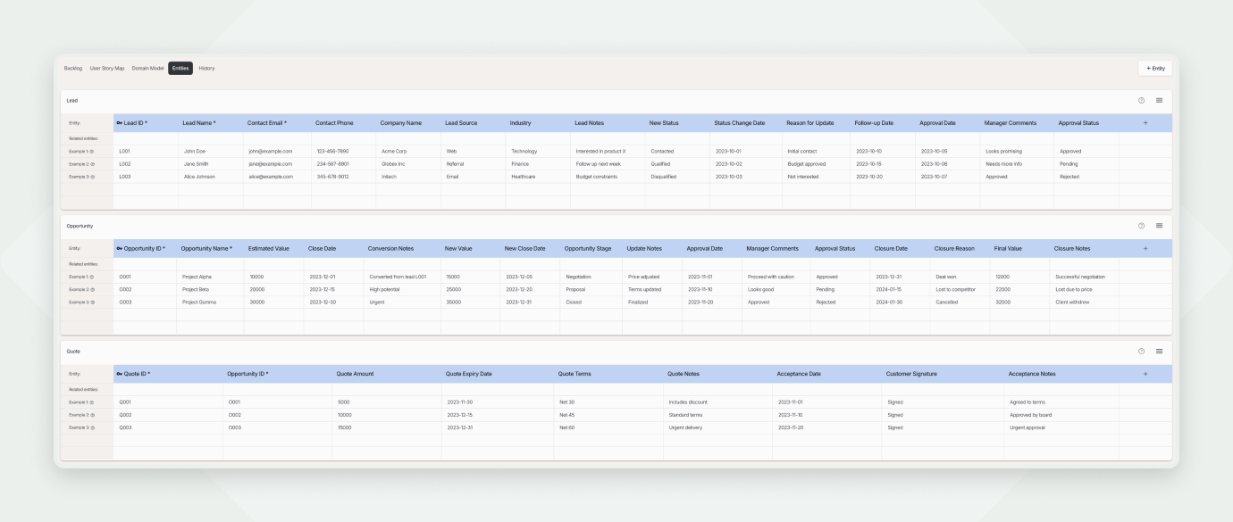
TIP: If you have an existing data store you want to use, you can import your Entities before generating the workflow diagram. The generated workflow will then be based on your imported Entities.

If more than one Command operates on one Aggregate Root, you will see Commands (boxes with blue borders) grouped around the Aggregate Roots. If you need to move a single Command to a different Aggregate Root, first select the corresponding Event, then change the Aggregate Root specifically for that Command (in the box with yellow borders).

Now it's time to review each Event and its details. Iterate through Steps 3 - 5 for each event. It is recommended to perform this review collaboratively with Domain Experts to validate assumptions and refine the model.
Let's start by selecting the first event: "Created lead". Inspect the workflow and the Domain Model. Ask the following questions and refine the model based on the answers.
1. Event Name & Actor:
2. Aggregate Root & Entity:
Note: Ensure the event you are reviewing represents a genuine state-changing action (like a create, update, or delete) on the identified Aggregate Root / Entity. If the event describes a query, a read operation, or something that doesn't fundamentally change the state of the core entity, it might not be a true Domain Event for this workflow. Consider removing it from this primary sequence for now (e.g., by deleting it or moving it to a separate analysis area/branch in Qlerify) and potentially modeling it differently (perhaps as a Read Model interaction, discussed later).
Now, let's focus on the Command associated with the event you are reviewing (the box with blue borders in the Domain Model). We need to define the data fields (parameters) required to execute this Command.
What information does a Sales Rep need to provide when creating a Lead? Open the sidebar in Qlerify and navigate to the "Data Fields" tab. This tab shows a simple mockup of the input form based on the Command.
Are the fields correct? Are any fields missing? Add, remove, or reorder fields in the Domain Model, directly inside the blue Command box, not in the mockup.

Note: The mockup is there to visualize what the system might look like, it shows example data but is not fully functional. For example a field might contain a drop down, but items cannot be selected.
Qlerify supports five main ways to model Command fields, corresponding to different data structures:
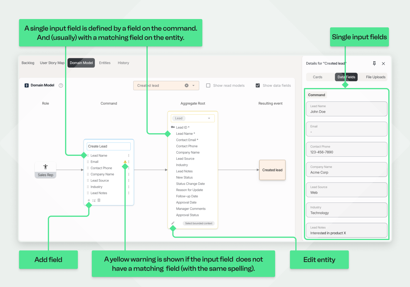
1. Single Input Fields (Primitive Types)
These represent single values like numbers, dates, text, or booleans. In the UI mockup they are shown as plain fields with labels and example data.
2. Single Reference to a Related Entity (By ID)
A reference is used when the Command carries a link to another Entity, located outside the current Aggregate boundary. The reference is typically made using the target Entity's ID.
In the UI mockup shown as a single select drop down.
Lead Aggregate boundary for this Command. The purpose of the mockup is just to visualize the interaction, it does not allow you to select items.
3. Multiple References to Related Entities (By IDs)
This field is similar to a single reference, but allows linking to multiple instances of another Entity. In the UI mockup it is shown as a drop down with checkboxes to indicate multi-select.

4. Collection of Entities (Nested items within Aggregate Boundary)
This type is used for collections of related entities that reside inside the Aggregate boundary for this command. In the UI mockup it is shown as a list of items, like order rows, where items can be added, edited and removed.
Lead Aggregate.Lead Aggregate boundary. The UI mockup will show the notes as a list of items.
5. Single nested Entity (Item within Aggregate Boundary)
This represents a single related entity (with its own fields) that is located inside the Aggregate boundary for this command. In the UI mockup shown as a sub form.
to this field. Set the cardinality to 1:1. Don't set it as a "Reference" type.
Now we can review the Aggregate boundary, for this Command, and and the Aggregate which is displayed inside the boundary.
Note: Aggregate boundaries are dynamic. The boundary visualized for a specific Command/Event shows only what's directly manipulated or included by that operation. When viewing the overall Domain Model without filtering by a specific Event, Qlerify typically shows an accumulated view, including all Entities that fall within the Aggregate boundary for any of its associated Commands.
The next step is to identify Read Models. Read Models represent the information (or views of data) an actor needs before executing a specific command. Think of them as queries that fetch relevant context to support decision-making or populate a user interface.
Not every event/command necessarily needs a preceding Read Model fetched from the system. For instance, the "Created Lead" event might be triggered externally (e.g., by a phone call) without the user first querying data within an application.
Let's now use a different event from our example workflow: "Converted lead to opportunity". Before a Sales Rep converts a Lead to an Opportunity, what data should the system present to them?
Now, let's define the necessary Read Models for this event:
Example 1: Listing Leads Available for Conversion
To convert a Lead, the Sales Rep first needs to select one. Let's define a Read Model to list relevant Leads.
Lead Entity.
Example 2: Listing Related Opportunities for Context
When selecting a Lead to convert, it might be helpful for the Sales Rep to also see if any Opportunities already exist for the same Company. Let's add a second Read Model for this.
Conclusion:
By defining Read Models like these, you specify the data needed before commands are executed. This helps design more user-friendly interfaces and ensures actors have the necessary context, improving the efficiency and effectiveness of the system.
A core concept in Domain-Driven Design (DDD) is the Bounded Context. We define Bounded Contexts to divide a large system into more manageable, logically consistent parts, helping to clarify scope, ownership, and the meaning of model elements within each context.
Now, let's assign Entities to their respective Bounded Contexts.
Observing the Results:
After assigning contexts, the Domain Model view should visually reflect this structure:
Context Map:
Qlerify also provides a part of a Context Map view. This view helps visualize the relationships and dependencies between different Bounded Contexts.
When viewing a single Bounded Context you will see integration points – places where commands in the current context trigger updates on Entities in other Bounded Contexts. These integration points are highlighted with the label "Integration with other bounded contexts".

You have now defined a comprehensive Domain Model within Qlerify, encompassing:
This Domain Model serves as powerful, living system documentation and provides a solid foundation for development, provided that it accurately reflects your actual domain logic. It's crucial to iterate on this model and keep it up-to-date as the understanding of the domain evolves or the system changes.
Now, one of the most exciting capabilities remains: leveraging this detailed Domain Model for code generation. Based on the structure you've meticulously defined, Qlerify can automatically generate API definitions (like OpenAPI specifications) and even a complete, runnable application, including a fully-featured backend, an interactive frontend, and a test suite derived directly from your business logic.
This generation process is typically performed per Bounded Context, reinforcing the modularity of your design.
The specific steps for initiating and configuring AI-assisted code generation are described in detail in a separate guide: the "AI Generated Code" article. You can find a link to this article in the footer of the page.
Eric Evans, the creator of DDD, joined the discussion (at the Virtual DDD Meetup mentioned earlier in this article) and raised thought-provoking questions. Key takeaways included:

To explore Qlerify and see how it can enhance your domain modeling process, sign up and start modeling today!
Watch the full Virtual DDD Meetup session: YouTube Video


